


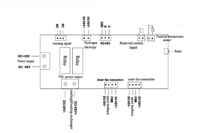
“MW4808034 controller system” is designed for the TEC cabinet air conditioning with automatic switching of a cooling and heating temperature control system. Two ways for fan output, respectively used for internal circulation and external heat exchange; refrigeration device can automatically switch heating and cooling output; hydrogen exhaust fan output, for replacement of the air circulating inside; it has a variety of fault alarm , dry contact relay output and LED indication, as well as voltage protection and remote monitoring, a remote PC equipment to monitor the performance of the temperature control system.
2.1 Technical parameters:
Technical Item | Unit | Parameters |
Ø Maximum voltage | VDC | 60 |
Ø Rated voltage | VDC | 48 |
Ø Rated current | A | 8 |
Ø Temperature range | ℃ | -40~110 |
Ø Temperature precise tolerance | ℃ | ±0.1 |
Ø Hydrogen fan | VDC/A | 48/3 |
Ø Internal circulation fan | VDC/A | 48/2 |
Ø Internal circulation fan | VDC/A | 48/2 |
2.2 Interface specification:
1)Power input DC48V.
2)NTC Sensor Interface
3)AC switch signal input interface (normally closed).
4)TEC working power output DC48V.
5)Exhaust fan hydrogen power MOS tube output DC48V
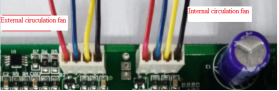
6)Inner fan Interface: Power +, PWM signal output, fan speed feedback signal, power -
7)Outer fan Interface: Power +, PWM signal output, fan speed feedback signal, power -
8)General alarm relay normally open / normally closed dry contact output
9)485 communication interface GND (do not take), 485B (T / R -), 485A (T / R +)
10)Display Interface (reserved)
11)Smoke control interface (reserved)
12)Humidity control interface (reserved)
13)Access control interface (reserved)
3 Temperature Control System Wiring
3.1 Electrical connection diagram
3.2 Electrical connection physical map
Please read《MW4808034 controller wiring scheme》
4 Product function
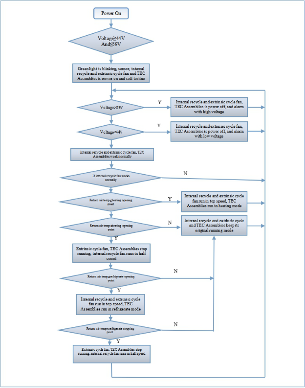
4.1 Self-test
After power (or press the RESET button) Start self-test function control panel, temperature sensor - outside the fan - internal cooling fan --TEC. Green light flashes when the self-test, hardware failure is detected by the red light for about 5 seconds, the self-test completed:
a.No alarm Green The normal operation of the control panel.
b.When an alarm is often red Steady green
4.2 Cooling
When the cabinet internal temperature is higher than opening point of refrigeration ,it starts the cooling operation, when the temperature is below the cabinet refrigeration stop point, the cooling operation is stopped. When setting the cooling temperature point, stop point temperature should be below opening point temperature.
Cooling point parameters setting
Parameters | Default value | Setting Range | Description | Description for setting point |
Refrigeration opening point | 25 | [20~45] | ℃ | The temperature point is set when the refrigeration operation starts to run |
Refrigeration stopping point | 15 | [10~35] | ℃ | The temperature point is set when the refrigeration operation stops to run |
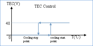
 Turn on TEC and closed it again, the outer circulation fan will delay 20 seconds before shutdown.
4.3 Heating
It begins the heating operation when the cabinet internal temperature is below the heating opening point. The cooling operation is stopped when the temperature is higher than the cabinet cooling stop point. Stopping point temperature should be higher than opening point temperature,when set the cooling temperature point.
Heating parameters setting
Parameters | Default value | Setting Range | Description | Description for setting point |
Heating opening point | 5 | [0~15] | ℃ | The temperature point is set when the heating operation starts to runt |
Heating stopping point | 15 | [10~20] | ℃ | The temperature point is set when the heating operation stops to run |
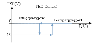 Turn on TEC and closed it again, the outer circulation fan will delay 20 seconds before shutdown.
4.4Internal circulation fan control
In the range of refrigerate point and heating point, internal circulation fan is running slowly at 2500 rpm (speed can set as your own). When the temperature reach refrigerate point or heating point, TEC start to work, internal circulation fan is running quickly at 2500 rpm (speed can set as your own)
Internal circulation fan control chart
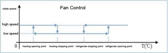
4.5 External circulation fan control
When the temperature reach refrigerate point or heating point, TEC start to work, external circulation fan is running quickly at 2850 rpm(speed can set as your own).
External circulation fan control chart
 Turn on TEC and closed it again, the outer circulation fan will delay 20 seconds before shutdown.
4.6 Dehydrogenating fan control
Dehydrogenating fan output can be directly with DC ventilator. Hydrogen discharge time is 5 minutes, 24 hours interval is adjustable.
Dehydrogenating parameters setting
Parameters | Default Value | Set Range | Description | Set Point Description |
Dehydrogenating period | 24 | [1-100] | hours | dehydrogenating period of start-up |
Dehydrogenating working time | 5 | [1-30] | minutes | dehydrogenating opening time |
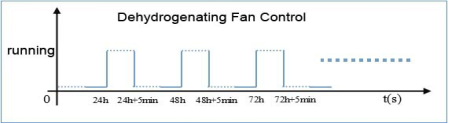 Dehydrogenating fan connector is “active output”,please do not short connect it.
4.7 Fault Alarm
The temperature control system has the function of fault detection and fault alarm. Below is the condition and phenomenon for alarm:
Parameters | Default Value | Set Range | Unit | Description | External Fan | The Reaction of TE When Alarming |
high temperature alarm | 55 | [30 –55] | ℃ | trigger point of high temperature alarm | Keeping working | Keeping working |
low temperature alarm | 0 | [-40 –10] | ℃ | trigger point of low temperature alarm | Keeping working | Keeping working |
Internal recycle fan default alarm | -- | -- | -- | / | Stop working | Stop working |
Extrinsic cycle fan default alarm | -- | -- | --
| / | Stop working | Stop working |
TE module default alarm | -- | -- | -- | / | Stop working | Stop working |
Over voltage default alarm | 59 | -- | -- | Voltage input≥59VDC | Keeping working | Keeping working |
Under voltage default alarm | 44 | -- | -- | Voltage input≤44VDC | Keeping working | Keeping working |
NTC sensor alarm | -- | -- | -- | Sensor fault | Keeping working | Keeping cooling |
If any of the above condition appears, the indicator light of alarm turn red.Warning output: Divided into “relay dry contacts output” and “LED indicator light output”.
Relay dry contacts please see the chapter of <temperature control system interface>. LED indicator light output please see the chapter of <LED indicator light>.4.8 Remote Monitoring
Temperature control system has the function of RS485 and remote monitoring, it can monitor the condition of temperature control system in real time through remote monitor software.
5 Temperature Control System Interface
5.1Power Interface
The chart below, you can find the definition of power interface, and also please consult the picture below.
Interface Name | Interface Function | Wire Specification | Remarks |
Power+ | The DC Power input into positive plate | 18AWG Red |
|
Power- | The DC Power input into negative plate | 18AWG Black |

5.2 Sensor Interface
The chart below, you can find the definition of sensor interface, and also please consult the picture below
Interface Name | Interface Function | Wire Specification | Remarks |
NTC | NTC |
| No distinction electrode |
NTC | NTC |
| No distinction electrode |

5.3 TEC Interface
The chart below, you can find the definition of TEC interface, and also please consult the picture below.
Interface Name | Interface Function | Wire Specification | Remarks |
NTC | NTC |
| No distinction electrode |
NTC | NTC |
| No distinction electrode |
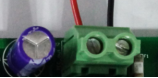
5.4 Fan Interface
The chart below, you can find the definition of fan interface, and also please consult the picture below.
Interface Name | Interface Function | Wire Specification | Remark |
DC48V+ | The fan interface input into positive electrode | RED | Internal (External) |
PWM speed governing | Fan speed-transfer | BLUE | Internal (External) |
speed feedback | Fan speed test | YELLOW | Internal (External) |
DC48V- | The fan interface input into negative electrode | BLACK | Internal (External) |
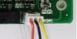
The chart below, you can find the definition of dehydrogenating interface, and also please consult the picture below.
Interface Name | Interface Function | Wire Specification | Remark |
H+ | The Dehydrogenating fan input into positive electrode | Red |
|
H- | The Dehydrogenating fan input into negative electrode | Blue |
 For battery-free freezer, this interface can be ignored.
The chart below, you can find the definition of fan interface, and also please consult the picture below.
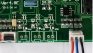
Interface Name | Interface Function | Wire Specification | Remark |
NO | Normally open dry contact | Red | The internal switch connected to COM in case of failure |
COM | common port | Black | Public interface |
NC | Normally closed dry contact | Yellow | The internal switch connected to COM under no-fault |
 If alarm Interface is not connected, it will not affect the function of temperature control system.Dry contact, referring to the passive output. Only a relay switch. Specific reference to the connection 《MW4808O34 temperature control system wiring diagram》
5.7 Remote Monitoring Interface
The chart below, you can find the definition of remote monitoring interface, and also please consult the picture below.
Interface Name | Interface Function | Wire Specification | Remark |
A | RS485 differential positive electrode | RED |
|
B | RS485 differential negative electrode | BLUE |
|
GND | Ground Wire | BLACK | can be left open |
There are two kinds of color on the control panel, below is the definition:
LED | Statements | Colors | Indicator status | Definition |
Power indicator light | Normal operation | GREEN | LIGHTING | Normal operation |
FLASHING | Self test | |||
OFF | No power | |||
Alarm indicator light | Alarm | RED | LIGHTING | Default |
OFF | No alarming |
7 Product usage
1、Interface Operation(Reserved)
2、Remote Control Operation
Refer to “MW temperature controlling system instruction manual”