


“TM4810034 temperature control system”temperature control panel is designed for the semiconductor cooler to adjust the environment temperature, it can control the semiconductor when it works under the condition of cooling or heating. The temperature control panel can not only adjust the environment temperature, but also monitor the inner and external fan, temperature sensor, the situation of over pressure or under pressure and so on. If there is any abnormal, it will report alarm message through relay dry contacts. Real-time monitor toward the working mode of semiconductor is implemented by RS485 serial port, upper machine software and connection of communication port for temperature control panel.
2.1Technical Parameter:
Technical Term | Unit | Parameter |
Ø Max Voltage | VDC | 60 |
Ø Rated Voltage | VDC | 48 |
Ø Rated Current | A | 10 |
Ø Measuring Range | ℃ | -40~110 |
Ø Temperature Measurement Accuracy | ℃ | ±0.1 |
Ø Dehydrogenating Fan | VDC/A(VAC/A) | 30/5(250/5) |
Ø Internal Recycle Fan | VDC/A | 48/2 |
Ø Extrinsic Cycle Fan | VDC/A | 48/2 |
2.2 Interface Spec.:
1)Power input DC48V.2)NTC temperature sensor interface
3)TEC working power supply DC48V.
4)Dehydrogenating Fan out put interface
5)Internal recycle fan interface: power supply+, PWM signal output, fan speed signal feedback, power supply-.
6)Extrinsic cycle fan interface: power supply+, PWM signal output, fan speed signal feedback, power supply-.
7)Alarm relay normally open/Normally closed dry contact output
8)485 communication interface GND(can be left open), 485B(T/R-), 485A(T/R+)
9)DIF(reserved)
3 Temperature Control System Connection
3.1 The Schematic Diagram of Electrical Connection
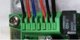
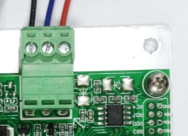
3.2 The Physical Map of Electrical Connection
Please refer to《TM4810O34 temperature control system connection》4 Product Function
4.1 Self Test
When power on, the temperature controlling panel starts to self test: temperature sensor- internal recycle fan- extrinsic cycle fan- TEC refrigerate. When self testing, the green light is blinking.If hardware failure, the red light will blink. When self testing finish: a.No failure warning, the controlling panel works normally. b. If there is a alarming, the green light will be off and the red one will be blinking.
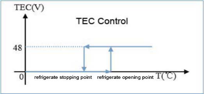
4.2 refrigerate
When temperature inside cabinet higher than the opening point of refrigeration, the refrigeration operation starts to run; when temperature lower than opening point, it stops. When setting the point, the stopping point should be lower than the opening one
refrigeration technical parameter
Parameter | Default Value | Set Range | Description | Set Point Description |
Refrigeration opening point | 30 | [15~55] | ℃ | The temperature point is set when the refrigeration operation starts to run |
Refrigeration stop point | 25 | (10~55) | ℃ | The temperature point is set when the refrigeration operation stops to run |
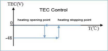
4.3 Heating
When temperature inside cabinet lower than the opening point of heating, the heating operation starts to run; when temperature higher than stopping point of refrigeration, it stops the refrigeration operate. When setting the point, the stopping point should be higher than the opening one.
Parameter | Default Vaule | Set Range | Description | Set Point Description |
Heating opening point | 5 | [-10~20] | ℃ | The temperature point is set when the heating operation starts to run |
Heating stop point | 15 | (-10~30) | ℃ | The temperature point is set when the heating operation stops to run |
Heating running chart:
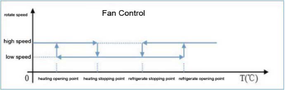
4.4 Internal Recycle Fan Control
In the range of refrigerate point and heating point,the internal recycle fan runs in a low speed. When the temperature reach refrigerate point or heating point, TEC start to work, the internal recycle fan runs in high speed.
Internal recycle fan control chart:
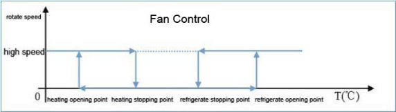
4.5 Extrinsic Cycle Fan Control
When the temperature reach refrigerate point or heating point, TEC start to work, the extrinsic cycle fan runs in high speed.。
Extrinsic cycle fan control chart:
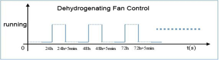
4.6 Dehydrogenating Fan Controlling
The dehydrogenating fan output can be with DC exhaust fan. The time for dehydrogenating is 5minute, time interval is adjustable within 24 hours.
Parameter | Default Value | Set Range | Description | Set Point Description |
dehydrogenating period | 24 | [1-24] | hours | dehydrogenating period of start-up |
dehydrogenating working time | 5 | [1-30] | minutes | dehydrogenating opening time |
dehydrogenating fan working control chart
4.7 Fault Alarm
The temperature control system has the function of fault detection and fault alarm. Below is the condition and phenomenon for alarm:
Parameter | Default Value | Set Range | Unit | Description | External Fan | The Reaction of TE When Alarming |
high temperature alarm | 55 | [30 –55] | ℃ | trigger point of high temperature alarm | Keeping working | Keeping working |
low temperature alarm | 0 | [-40 –10] | ℃ | trigger point of low temperature alarm | Keeping working | Keeping working |
Internal recycle fan default alarm | -- | -- | -- | / | Stop working | Stop working |
Extrinsic cycle fan default alarm | -- | -- | --
| / | Stop working | Stop working |
TE module default alarm | -- | -- | -- | / | Stop working | Stop working |
Over voltage default alarm | 58 | -- | -- | Voltage input≥58VDC | Keeping working | Keeping working |
Under voltage default alarm | 39 | -- | -- | Voltage input≤39VDC | Keeping working | Keeping working |
NTC sensor alarm | -- | -- | -- | Sensor fault | Keeping working | Keeping cooling |
!!!If any of the above condition appears, the indicator light of alarm turn red.
Warning output: Divided into “relay dry contacts output” and “LED indicator light output”.
!!!Relay dry contacts please see the chapter of <temperature control system interface>.
!!!LED indicator light output please see the chapter of <LED indicator light>.
4.8 Remote Monitoring
Temperature control system has the function of RS485 and remote monitoring, it can monitor the condition of temperature control system in real time through remote monitor software.
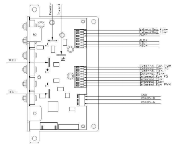
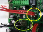
5.1 Power Interface
The chart below, you can find the definition of power interface, and also please consult the picture below.
Interface Name | Interface Function | Wire Specification | Remarks |
Power+ | The DC Power input into positive plate | 18AWG Red |
|
Power- | The DC Power input into negative plate | 18AWG Black |
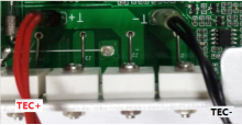
5.2 TEC Interface
According to the chart below, you can find the definition of TEC interface, and also please consult the picture below.
Interface name | Interface function | Wire specification | Remark |
TEC+ | TEC input into positive electrode | 18AWG Red |
|
TEC- | TEC input into negative electrode | 18AWG Black |
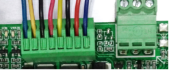
5.3 Fan Interface
According to the chart below, you can find the definition of Fan interface, and also please consult the picture below.
Interface Name | Interface Function | Wire Specification | Remark |
Internal Fan+ | The fan interface input into positive electrode | RED | Internal Circulation(Third from right) |
Internal Fan PWM | Fan speed-transfer | BLUE | Internal Circulation(First from right) |
Internal Fan FG | Fan speed test | YELLOW | Internal Circulation(Fourth from right) |
Internal Fan- | The fan interface input into negative electrode | BLACK | Internal Circulation(Third from right) |
External Fan+ | The fan interface input into positive plate | RED | Extrinsic cycle(Fourth from left) |
External Fan PWM | Fan speed-transfer | BLUE | Extrinsic cycle(First from left) |
External Fan FG | Fan speed test | YELLOW | Extrinsic cycle(Second from left) |
External Fan- | The fan interface input into negative plate | BLACK | Extrinsic cycle(Third from left) |
5.4 Other Interfaces
Other interfaces including NTC, default dry contacts, hydrogen discharging interface. According to the chart below, you can find the definition, and also please consult the picture below.
Interface name | Interface function | Wire specification | Remark |
Exhausting Fan- | dehydrogenating fan input into negative electrode | BLACK | First from left |
Exhausting Fan+ | dehydrogenating fan input into positive electrode | RED | Second from left |
ALM- | Alarming dry contact | BLUE |
|
| / |
|
|
ALM+ | Alarming dry contact | RED |
|
NTC- | NTC Sensor Interface | BLACK |
|
NTC+ | NTC Sensor Interface | BLACK |
!!!To refrigerated cabinet without storage battery, the dehydrogenating fan interface can be ignore.
!!!Without connecting to the alarm interface, it has no effect on the function of temperature system.
!!!Dry contact refers to passive output. Just relay switching. The mode of connection please see “TM 4810O34 Temperature control system connection diagram”
5.5 Remote Control Interface
According to the chart below, you can find the definition of remote control interface, and also please consult the picture below.
Interface Name | Interface Function | Wire Specification | Remark |
A | RS485 differential positive electrode | RED |
|
B | RS485 differential negative electrode | BLUE |
|
GND | Ground Wire | BLACK | can be left open |
6 LED Indicator Light
There are two kinds of color on the control panel, below is the definition:
LED | Statements | Colors | Indicator status | Definition |
Power indicator light | Normal operation | Green | Flashing | Self test/Normal operation |
OFF | Power-down/default | |||
Alarm indicator light | Alarm | Red | Flashing | Default |
OFF | Power-down/without alarming |
7 Product Usage
1、Interface Operation(Reserved)
2、Remote Control Operation
Refer to “TM temperature controlling system instruction manual”
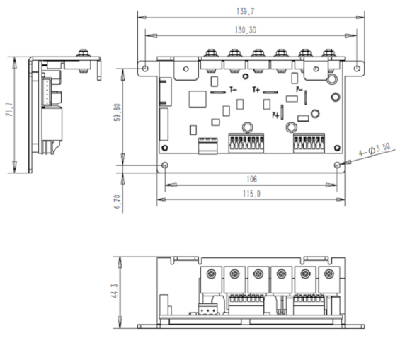
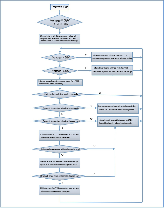
8 Operation Flow Chart
9 Dimension Size Chart