


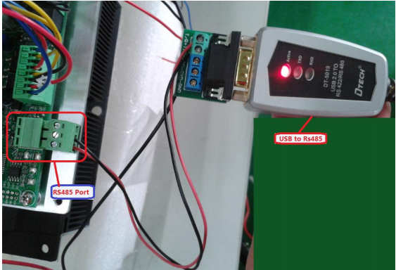
As shown in the figure below, please turn "USB RS485" connected to the temperature control panel of the RS485's A and B line.
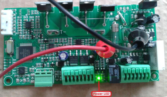
Open the power which connected to the temperature control plate, then the Temperature control board's green light will be flashing, indicates that the system connect electric is successful.
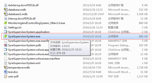
III、 Start the software
Double-click the icon file, open the application.
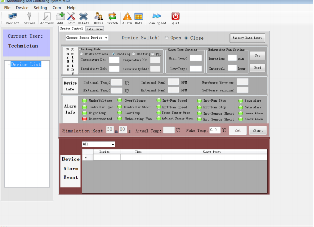
Application software interface as shown in the figure below.
IV、 Add equipment
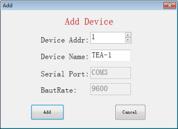
Click the icon ,enter the add dialog of equipment, as shown in the figure below.
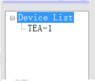
„Device Addr‟ you can choose, „Device Name‟ you can customize, after finished click the "Add", at this time you can see the number of type list "Device List", a new item "TEA-1" shown in the figure below.
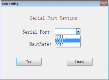
V、 Serial port setting
Click on the icon ,enter the "Serial port setting" dialog,choose "Serial port",said you currently use "USB to Rs485" in COM port.
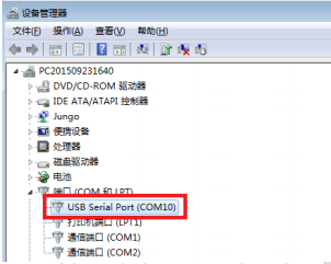
You can check the "USB to Rs485" in COM port via "DevManView"(see below picture)
Click on the icon
 , make the icon become
 ,If normal communication, then the software will read temperature control panel information, information is divided into:Parameter Settings,Equipment information,Alarm information.
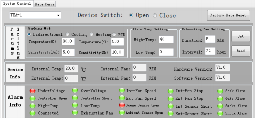
Equipment information:temperature, fan speed, etc.
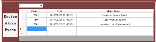
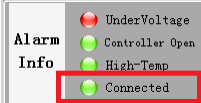
Alarm information:If showing red , it says this information is flipped or alarmed, and the alarm information will record to the database, as shown in the figure below:
In communications,if communication is successful, then will prompt in the alarm information.
In the red box said communication success, if the communication failure,then in the warning bar will appear.
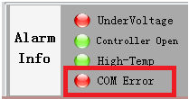
In the red box said communication error. At this point you need to check if the temperature control board is powered (If the LED flash), and whether the RS485 port is disconnected.If apper 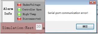 Said the USB is offline.
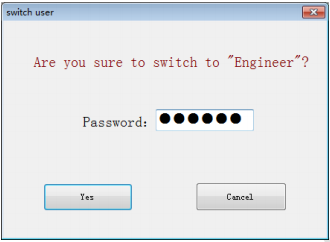
VII、 Switch the user
If you're an engineer or clear about the parameters of temperature control board, then this section will begin to enter engineer mode Click on the icon  ,enter the dialog box of "Switch user‟, input character “888888”,click
If you're an engineer or clear about the parameters of temperature control board, then this section
will begin to enter engineer mode
Click on the icon
,enter the dialog box of „Switch user‟, input character “888888”,click„yes‟, then you can enter „Engineer‟。 After entering the interface which indicated 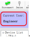 ,
,
it means you are "Enginee‟ users.
VIII、 Set the parameters
In "Params Setting‟ as below picture
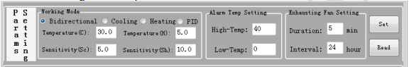
The following is a brief introduction for parameters:
Working Mode
Bidirectional: Desired temperature control board automatically switches the cooling and heating
Cooling:Desired temperature control board only heating but not cooling.
Heating:Desired temperature control board only cooling but not heating.
PID:Desired control mode is PID algorithm for temperature control.
Temperature(C):Cooling point temperature, when the ambient temperature is higher than the value of this edit box, thermostat begin cooling
Sensitivity(sc):During cooling, when the ambient temperature is below „Temperature (C) -Sensitivity (sc)‟, stop cooling
Temperature(H):System hot spot temperature, when the ambient temperature is below the value of this edit box, the thermostat starts heating
Sensitivity(sh):During heating, when the ambient temperature is higher than „Temperature (H)
+ Sensitivity (sh)‟, stop heating
Alarm Temp Setting
High-Temp:High temperature alarm, when the ambient temperature is higher than the value of this edit box, thermostat temperature warning appears
Low-Temp: Low temperature alarm, when the ambient temperature is below the value of this edit box, thermostat temperature warning appears Exhausting Fan Setting
Duration:Hydrogen exhaust fan opening time
Interval:Hydrogen exhaust fan cycle
IX、 Simulation Test
In the following chart click the „Start‟ button, enter the simulation tests


Automatically exit simulation test countdown after 30min.